← Home · Seismic

Soil Liquefaction Analysis in Knoxville: ASTM D1586 and IBC Compliance

Together, we solve the challenges of tomorrow.

SEE MORE →

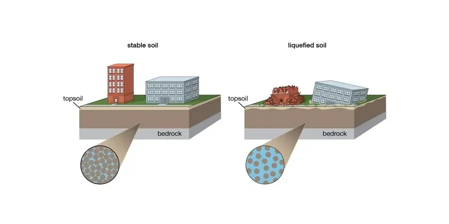
IBC Section 1803.5.12 requires liquefaction evaluation in Seismic Design Category D, E, or F when shallow groundwater is present. In Knoxville, that means any site within the Tennessee River and Holston River alluvial corridors gets flagged during plan review. The Tennessee River's floodplain deposits—loose sands and silts with water tables often within 6 feet—meet the classic criteria for flow liquefaction under the New Madrid Seismic Zone influence. Our lab runs the full SPT drilling sequence with split-spoon energy-corrected N-values, then applies the NCEER/Youd-Idriss (2001) simplified procedure to compute factor of safety against liquefaction. For sites where SPT refusal hits before 50 feet, we switch to CPT testing to get continuous tip resistance and sleeve friction profiles without losing data in the critical upper 30 meters.

Loose alluvium plus shallow groundwater equals mandatory liquefaction screening under IBC—no exceptions in Seismic Design Category D.

Process overview

A recent mixed-use project off Neyland Drive sat on 14 feet of loose alluvium overlying weathered shale—classic Knoxville stratigraphy. The geotechnical report required liquefaction triggering analysis because the groundwater was at 4.5 feet and the site is within 3 miles of a known seismic source. We mobilized a CME-75 drill rig, performed SPT sampling at 2.5-foot intervals through the sand layer, and collected thin-wall Shelby tubes for cyclic triaxial testing on representative specimens. The data fed directly into a site-specific PGA of 0.18g from the USGS hazard model. Post-processing included fines content correction from grain-size analysis and Atterberg limits to confirm that the silty sand was indeed liquefiable under the Seed et al. (1985) curve. Settlement estimates using Tokimatsu-Seed (1987) integration showed up to 3.2 inches of differential movement, which drove the structural engineer toward a rigid mat foundation design. The whole sequence—from rig setup to signed report—took seven working days.
Soil Liquefaction Analysis in Knoxville: ASTM D1586 and IBC Compliance
Technical reference image — Knoxville

Local context

The CME-75 drill rig we deploy on Knoxville liquefaction jobs carries a 140-pound automatic trip hammer with an energy ratio calibrated at 60% via instrumented rod testing. That energy correction matters: an uncalibrated donut hammer can overestimate N-values by 30%, producing falsely optimistic factor of safety numbers. We run the hammer at a steady 30-40 blows per minute through the saturated zone, changing from hollow-stem augers to mud rotary if the sand collapses at depth—common in the Second Creek drainage basin where loose hydraulic fill from 1920s railroad construction still exists. Every SPT spoon is photographed, logged for recovery, and sealed in a plastic liner for transport to our ASTM D422-compliant lab. For sites requiring seismic microzonation, we supplement SPT data with MASW surface wave profiles to map Vs30 and assign NEHRP site class.

Need a geotechnical assessment?

Reply within 24h.

Email: contact@geotechnicalengineering.biz

Technical parameters


ParameterTypical value
Analysis methodNCEER/Youd-Idriss (2001) simplified procedure
Field test standardASTM D1586-18 (SPT) or ASTM D5778-20 (CPT)
Corrected blow count(N1)60cs using energy ratio, overburden, and fines content
Cyclic stress ratio (CSR)CSR = 0.65 × (amax/g) × (σv/σ′v) × rd
Cyclic resistance ratio (CRR)CRR from SPT-based curve (Seed et al. 1985, updated by Youd et al. 2001)
Factor of safetyFS = CRR/CSR; minimum acceptable FS ≥ 1.1 per IBC
Groundwater monitoring24-hour stabilized readings in open borehole or piezometer
Post-liquefaction settlementTokimatsu-Seed (1987) or Ishihara-Yoshimine (1992) volumetric strain integration

Additional services

01

SPT-Based Liquefaction Triggering

Energy-corrected N-values with fines content adjustment. We compute CSR from the USGS seismic hazard curve for the Knoxville quadrangle and CRR from the Youd-Idriss curve, delivering FS profiles at 2.5-foot increments.

02

Cyclic Triaxial Testing (ASTM D5311)

Undrained cyclic loading on undisturbed Shelby tube samples at confining pressures matching field overburden. Generates cyclic strength curves for site-specific CRR calibration.

03

Post-Liquefaction Settlement Analysis

Volumetric strain integration using Tokimatsu-Seed or Ishihara-Yoshimine methods. Outputs include differential settlement contours for foundation design.

04

Lateral Spreading Displacement Estimates

Empirical models (Youd et al. 2002, Bardet et al. 2002) applied to free-face and gently sloping ground conditions. Critical for riverbank sites along the Tennessee River.

Reference standards


IBC Chapter 18 (Soils and Foundations), Section 1803.5.12, ASCE 7-22, Chapter 21 (Site-Specific Ground Motion Procedures), ASTM D1586-18 (Standard Test Method for SPT and Split-Barrel Sampling), ASTM D2487-17 (Classification of Soils for Engineering Purposes), NCEER/Youd-Idriss (2001) consensus paper on liquefaction evaluation

Common questions

Does Knoxville actually need liquefaction analysis? We are not on the West Coast.

Yes, IBC requires it. Knoxville is in Seismic Design Category D due to proximity to the East Tennessee Seismic Zone and the influence of the New Madrid Seismic Zone. Any site with loose saturated sands and groundwater within 50 feet of grade triggers the evaluation.

What does a liquefaction analysis cost in the Knoxville area?

For a typical commercial site with two SPT borings to 50 feet, laboratory grain-size and Atterberg testing, and the complete triggering and settlement report, the range is US$2,430 to US$4,800. The final number depends on boring depth, number of samples, and whether cyclic triaxial testing is specified.

How long does the field and lab work take before we get the report?

Field drilling usually takes one to two days. Laboratory grain-size and Atterberg tests require three to four working days. The engineering analysis and signed report are delivered within seven to ten working days from rig demobilization.

What if the SPT refusal is shallow and we cannot get deep enough data?

If SPT refusal hits above the liquefiable zone, we switch to CPT sounding (ASTM D5778) which can push through dense layers without losing stratigraphic resolution. The CPT tip resistance and friction ratio data integrate directly into the Robertson (2009) liquefaction triggering method as an alternative to SPT-based analysis.

Location and service area

We serve projects across Knoxville and its metropolitan area.

View larger map